|
To
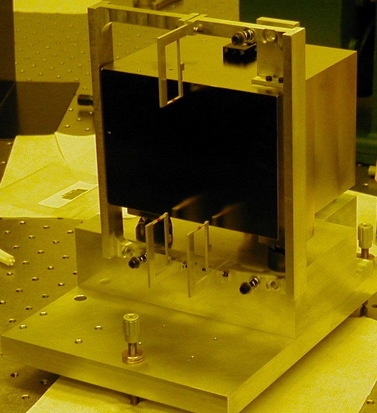
remove the effects of gravity sag, the optic must be held vertically within
70 arcsec. To achieve this, a flat surface is first used to establish a
vertical reference plane. The optic is then aligned parallel to that surface
using the flexure tilt stage. The flat surface is achieved through designing
an aluminum block that has a Nickel coated surface optically polished to
0.1 mm. This surface, referred to as the reference
flat, is made perpendicular to the top surface of the block to 1 arcsec,
where an inclinometer is mounted to indicate the horizontal plane with a
resolution of 14 arcsec. This block with the sensor is mounted onto the
device base plate supported on three adjustable fine-threaded (¼-100)
screws. By adjusting the screws until the inclinometer indicates close to
zero reading, the top surface is aligned with the horizontal plane and therefore
the reference surface perpendicular to the top one is aligned with the vertical
plane.
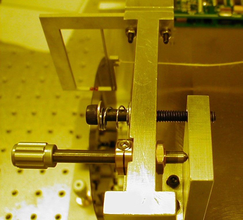
Flexure Tilt Stage
Once the polished surface of the aluminum block is properly adjusted to
achieve a vertical reference plane, the optic must be aligned with this
surface using an autocollimator. This means the double-sided flexures
that hold the optic must have two degrees of freedom in the pitch and
yaw directions. This is done by a vertical tilt stage that captures the
three double-sided flexures using three fine pitch screws as shown in
the figure below.
|
 |